

The Basic Components and Structure of a Thick Film Heater
A typical Thick Film Heater consists of several components or layers. Selection of dielectrics, conductors, and resistive inks, along with their combinations, is based on material properties and the thermal-electrical requirements of the TFH product. Additional considerations include application compatibility, such as operating temperature, cycle rates, watt density, and environmental conditions.
1. Substrate
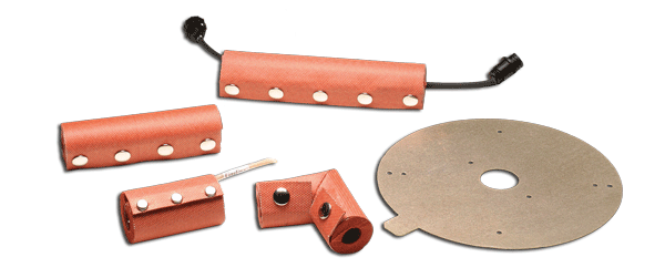
The substrate is the surface on which the heater is to be built or the surface facing the object to be heated. Commonly used base substrate materials are divided into a few classes: (1) Ceramics, such as the aluminum oxide (AL2O3) substrate, aluminum nitride (AlN), beryllium oxide (BeO), and zirconium oxide (ZrO2); (2) Stainless steel, such as types 304 and 430; (3) Aluminum; (4) Glass or Mica; (5) Surface treated rubber and plastics. For more information on the Thick Film Heater subtrates offered at Heatron, visit Thick Film Products and Services.
Substrate material is selected based on the choices of resistive pastes and conductor materials, all important components of a TFH. Compatibility with the application conditions or the operating environment, temperature, power requirements, and cost are important factors to consider for the selection of a substrate. Heatron’s design engineering team is experienced in analyzing the applications and proposing an optimized plan which is focused on boosting performance and containing costs in a timely manner.
2. Dielectric Layer
The dielectric layer is between the metallic substrate and the printed traces. The dielectric layer can be printed, coated, or laminated. The dielectric materials are generally glass and ceramic based and not conductive. This layer is particularly necessary if the substrate is metallic such as stainless steel or aluminum. The metal substrate must be electrically insulated from the printed traces of either resistive pastes or conductor material. The dielectric layer restricts leak current and ensures the electric integrity of the heater.
If an electrically non-conductive base substrate is selected, such as ceramic or non-metallic in nature, the dielectric layer may not be needed.
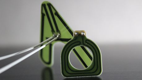
3. Heating or Resistive Traces
The resistive ink or paste is to be printed or coated onto the treated substate to form heating traces or paths; therefore, it is called “functional material” as it is responsible for generating heat in a TFH. The formula partially determines the resistivity or wattage of the heating traces or elements. The choice of materials and their concentrations have been investigated and optimized through extensive effort of research and development at Heatron. Heatron’s proprietary knowledge on the chemistry of the paste formula and electric engineering allows high compatibility and strong adherence between the ink and chosen dielectrics or substrates.
The functional resistive materials can be printed in two ways on the surface of the non-metallic substrate or the dielectric layer on top of the metallic substrate: printing the heating traces or pattern that are lines or circuits or coating the underlying surface with full coverage. In the first case, the conductor traces (to be discussed next) may not be needed, but in the second case, the conductor traces must be printed to allow electrification.
The pastes or inks can be developed to exhibit three different relationships between the resistivity or power output and temperature under which the device operates:
(1) ZTC – zero temperature coefficient of the resistance. The power output or watt density of heaters made with the ZTC formula does not change as a function of temperature. ZTC material is used in most types of TFHs. Examples of the ZTC ink or paste are mixing ceramics or glasses with metals and metal oxides, such as silver and ruthenium, in various combinations to obtain inks with different resistance values. This article addresses mainly the ZTC heaters.
(2) PTC – positive temperature coefficient of the resistance. The PTC heaters can self-decrease the power output when the temperature is increased, but output also increases automatically when the object to be heated becomes colder. PTC heaters can be divided into two classes based on the materials or application temperatures. The high-temperature class is made using polycrystalline ceramics containing key ingredients such as barium titanate (BaTiO3) which exhibits a PTC property above the Curie point of about 12°C. In the low-temperature class of the PTC TFHs, the formula of PTC paste is prepared by mixing conductive particles such as carbon black with semicrystalline polymers like polyethylene or per-fluorinated ethylene and their oligomers in either a solvent-based emulsion state or a molten state. The polymer and carbon based low-temperature heaters exhibit PTC effects monotonically between relatively low glass transition temperatures (-40°F or lower) and the melting point of the semicrystalline polymer. Heatron has developed prototypes of the low-temperature polymeric PTC heaters which can be used in medical diagnostics. The heater heats the blood sample with diminishing power as temperature rises. To facilitate the diagnostics, the temperature plateaus within a narrow range at so-called “limit temperature” as determined by the melting point of the polymer.
(3) NTC – negative temperature coefficient of the resistance. This type of device is known as “thermistor,” derived from the term thermally sensitive resistors, and can be used as a cost-effective sensor for accurate temperature measurements. This class is not included in this article.
4. Conductor Traces
The conductor traces are typically precious metal particles such as silver, palladium, gold or platinum, and their respective alloys.
Conductor traces are printed to apply voltage onto resistive traces and generate heat. As mentioned above, sometimes the voltage may be applied directly onto the resistive traces. Therefore, the preparation and printing of conductor traces are not required. However, if the heater substrate or the dielectric layer is coated continuously with a layer of resistive material, then conductor traces are necessary to apply voltage.
5. Protective Layer
Commonly used non-metallic materials for protective coatings include polymers, epoxies, and ceramics, depending on application conditions and the environment. The protective layer for TFHs is printed or coated continuously to cover the heater assembly and the sheath of the heater with several intents: electrically insulating the heating traces, mechanically protecting physical damage, chemically inhibiting or preventing corrosion along with water resistance, and thermally withstanding maximum application temperatures.
6. Connection Contacts
The contact points or areas allow for the attachment of lead wires by soldering, clamping, or welding. The contact points or areas can be the conductor materials described above. Metals with high electric conductivity can reduce contact resistance and create heat.
For more information about the structure of Thick Film Heaters, the fabrication process, advantages of TFHs, applications in the industry, and what Heatron's Thick Film Heaters have to offer to you, download our complete Thick Film Heating guide. This full guide provided by Heatron will allow you to develop a better understanding about TFHs so you can find the right one for your project(s).