

The Fabrication Process of a Thick Film Heater
A common Thick Film heating fabrication process is called screen printing. So, how is screen printing accomplished?
Step 1: Substrate Cutting
The shape or geometry of the substrate is dictated by that of the surface for the specified form factor. Depending on the substrate, the cutting is done by a laser or diamond saw according to the engineering drawing with the shape and dimensions as well as the sequence of the cutting action. The information or requirement on cutting is stored in the computer that controls the cutting.
Step 2: Dielectric or Insulation Printing or Coating
The glass or ceramic based dielectric material is prepared or emulsified into the form of ink or paste with the right viscosity by using an organic carrier or solvent. The dielectric emulsion is then printed, coated, or sprayed over the metal substrate.
In the case of a non-metallic substrate such as the ceramic substrate, this step may be skipped. Certain surface activation treatment may, however, be necessary to promote and enhance the bonding between substrate and printed traces.
Step 3: Ink Development or Formulation
Pastes or inks are commonly prepared by mixing or compounding the required ingredients, such as metal or metal oxides and ceramics, with a solvent to produce a paste for printing described in the next step. The mixing is typically done on a two or three-roll mill machine. The mixing must be microscopically dispersive so that a high degree of homogeneity between the mixing ingredients can be achieved. High paste homogeneity can eliminate hot spots and burnout for the finished parts.
The conductor material will also need to be made into a liquid state or in the form of a paste or ink for printing if needed.
Step 4: Stencil or Mask Fabrication for Screen Printing.
Stencils for screen printing on the substrate are usually a thin sheet of material, such as plastic and metal, with the pattern of heating traces cut from it. By using a squeegee to force the paste or ink through the cut-out patterns in the stencil, heating or conductor traces are transferred over to the surface of the underlying substrate.
The stencil determines the arrangement of heating traces and ultimately the pattern of heat distribution. It is designed to allow heating, where it is needed, according to the surface. The power density can be adjusted area by area by changing the stencil’s pattern to form a multi-zone TFH.
Step 5: Printing
The printing process is to deposit resistive and/or conductor traces onto the non-metallic substrate or the dielectric layer on the metal substrate. Many technologies to print films for electronics or heaters have been developed, but this article focuses on the screen-printing technology. Other interesting printing technologies will be briefly described.
Screen-printing has a long history and is the most simple, flexible, and economically friendly method. Screen-printing is still the most widely used process to make TFHs today. Printing is done by forcing the pastes or inks through engineered stencils, applying a squeegee onto a flat or cylindrical surface of a substrate. There are different methods of printing:
- The resistive traces are printed, using the stencil, onto the top of the precoated dielectric layer of the metallic substrate or directly onto the non-conductive substrate. Conductor traces may not be needed as the connections can be made directly onto the ends of resistive traces.
- After printing the resistive traces, conductor traces are printed to make connections with the resistive traces to form the circuit. The printing sequence maybe be reversed. Obviously, this method requires two different stencils or masks, one for resistive traces and one for conductor traces.
- Coat the resistive paste to cover the substrate completely, then, print the conductor traces to form circuits. The electric current flows through pathways with the least resistance.
The resistive traces or coatings are responsible to transform electric currents into heat. The conductor traces apply voltage onto the resistive traces.
The deposition process using screen-printing allows for close control of the thickness and width of the traces or heating elements, thus accurately controlling the heater resistance, wattage, watt density, and uniformity of the heated part.
Step 6: Curing or Firing
In this step, a printed heater undergoes heat treatment to make a strong bonding between the substrate or dielectrics and the printed traces. The early stage of curing or firing evaporates any liquid that is used in the step of paste preparation. During the firing process, the metal and metal oxide particles in the ink are bonded by virtue of sintering in the solid state. The bonding forms a morphology in which a network of many nanoscales electrically conductive pathways emerges, which becomes the permanent heating traces or elements. During the firing process, the glass particles are melted. This molten material fills up the interstitials between the traces and substrate which then bonds the entire structure to attain high mechanical strength. At the same time, the structure keeps a certain degree of bendability because the ratio between thickness and lateral dimensions is very small.
Heatron has developed temperature profiles that are optimized for the processes of bonding, involving various pairs of substrates and inks.
Step 7: Finishing steps - Protective Layer and Electric Termination
The protective layer on top of the heating traces is a dielectric material that provides insulation. The non-metallic protective layer, such as polymer or epoxies, maybe printed, coated, or sprayed on.
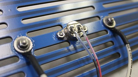
Various metals and alloys can be used for making the termination: silver, platinum, gold, and silver alloys. The attachment of lead wires can be done by spring contacts, soldering, and ultrasonic wire bonding. The connection points or areas can be encapsulated using epoxy or silicon RTVs. Visit Heatron's Thick Film Heating Products and Services for more information on the products offered at Heatron.
Step 8: Final quality inspection typically consists of tests such as:
- Resistance of the heater which determines the power output or total wattage.
- Insulation resistance (IR) between electrodes and ground such as the metal substrate using a voltage between 500 to 1,000 Vdc depends on intended application.
- Dielectric testing or hi-pot between electrodes and outer metal substrate or ground with an applied voltage of 2 times rated application voltage plus 1000 Vac.
- Performance active testing to measure the current and wattage under the rated voltage.
- Thermal imaging to determine surface temperature and uniformity.
- Service lifetime testing which is an accelerated performance active aging test done by cycling the temperature and voltage on/off for specific duty cycles and the duration of the test.
For more information about the structure of Thick Film Heaters, the fabrication process, advantages of TFHs, applications in the industry, and what Heatron's Thick Film Heaters have to offer to you, download our complete Thick Film Heating guide. This full guide provided by Heatron will allow you to develop a better understanding about TFHs so you can find the right one for your project(s).